# Hardware setup
### Setup:
1. Ensure the battery is **not** connected to the Analog Power Module.
2. Connect the APM to the Agam Autopilot v6X-RT**™** POWER1 and ADIO connectors as shown in Figure 1. To craft the cable on the Autopilot side,
* Use a MOLEX CLIK-mate 2.00mm pitch 6-pin connector, this connector is used to power the APM.
* **Pin 1**: Route 5V power from the APM connector. \
In case your APM works at 3.3V VDD, you will need to route via some other appropriate port on the Autopilot, such as the DSM port with a JST-ZH 1.5mm pitch 3-pin connector.
* **Pin 6**: Route GND from the APM connector.
* Use a JST-GH 1.25mm pitch 8-pin connector, this connector is used for the ADC input data.
* **Pin 6**: Route V\_SENSE signal from the APM connector.
* **Pin 7**: Route I\_SENSE signal from the APM connector.
3. Connect the Autopilot to your computer via USB.
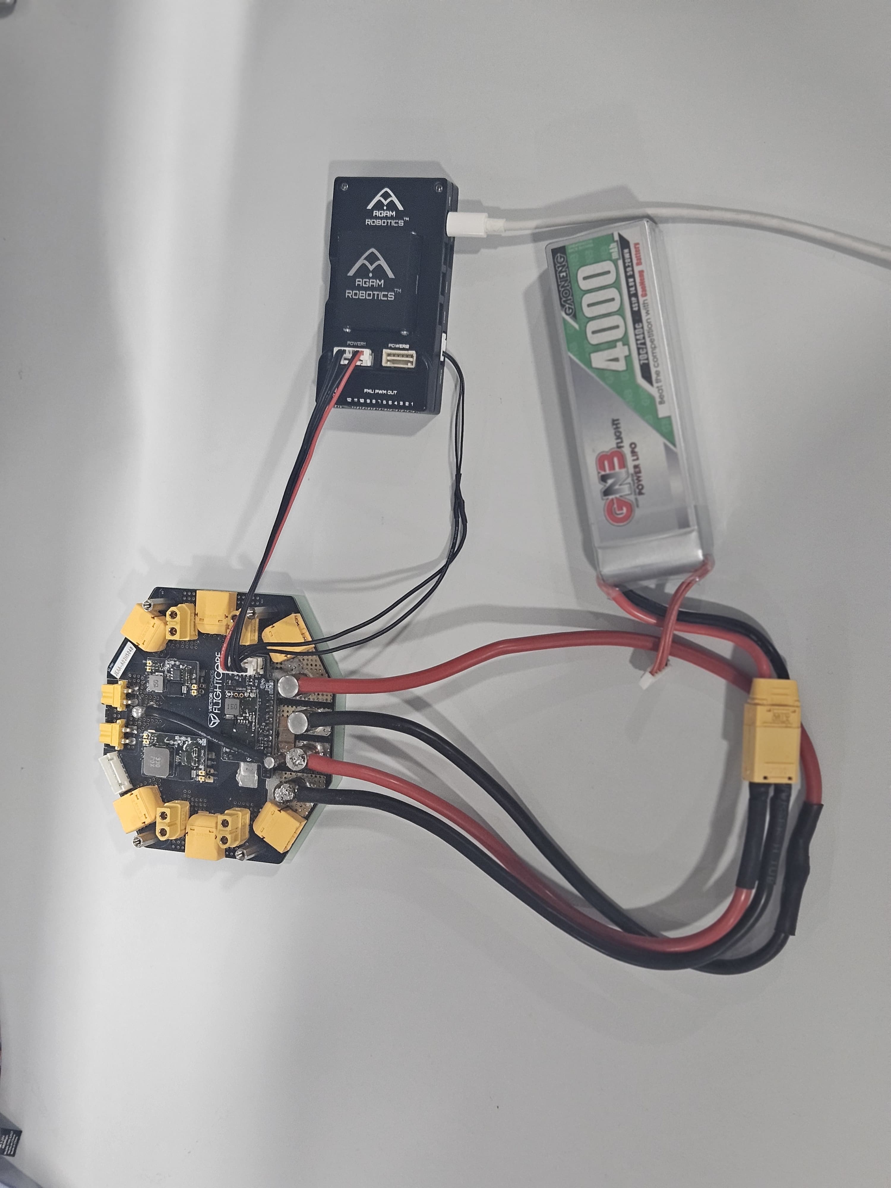
4. Connect the Battery to the APM. The complete setup is shown in Figure 2.
5. Proceed to setup the APM on your Ground Control software.
.jpeg?alt=media&token=0b452669-1d85-43d7-9d67-4b48ca72a799)